
Inductors Resonance
We'll start with the inductor!
 The Inductor
This figure shows a conductor carrying a current. A magnetic field is set up around the conductor as concentric circles.
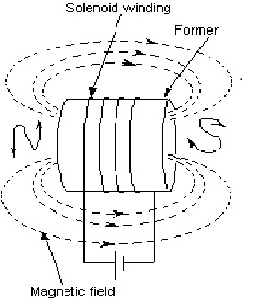
If a coil of wire has a current flowing through it, the magnetic flux due to each turn will link with every other turn and produce the same sort of magnetic field as a permanent magnet. Such a coil is called a solenoid as shown here. It acts as a magnet only when current is flowing through it.
The magnetic polarity of the solenoid can be determined from the 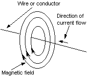 direction of current flow as seen looking in the ends, as shown in the diagram. From that the direction in which the magnetic field is acting can also be found.
Solenoids or electromagnets are widely used in electronic equipment. Loudspeakers, headphones, moving coil microphones, measuring instruments, transformers and such things, depend on electromagnetism for their operation.
A inductor may be air-cored or have a solid core.
Magnetic materials
Magnetic materials in common use for the cores of solenoids are:
Soft iron: easy to magnetise and demagnetise. Used for motor pole-pieces.
Silicon iron: used for transformer laminations and AC motors. Low-loss.
 Nickel iron alloy: also known as radio metal and mu-metal, is used for high-class audio transformers and cathode-ray tube screens.
Ferrites: iron oxide based materials used for a wide range of applications in radio and electronics generally. The characteristics depend on the mix of materials in the core and is extremely varied. Also known as ferroxdure and ferroxcube.
Permanent magnets: tungsten steel, and alloys of iron, nickel, aluminium, cobalt, ceramic, and titanium are used. Iron oxides can also be used.
The magnetic field surrounding a coil does not appear immediately the circuit is connected. It takes time to grow from nothing at the moment of switch-on to its maximum. The time taken for this depends on many factors, including the number of turns in the coil, the current, the core material, and the self-resistance of the coil. Similarly, when the current is switched off the field takes time to decay.
It should be noted that the current in the coil takes time to rise to its maximum. This must be compared to the capacitor where at switch-on, the voltage across the capacitor takes time to rise to its maximum (see below).
Inductors in series and parallel
A coil has inductance, measured in henries. The values of inductance used in radio range from several henries (H) to parts of a microhenry (µH). The inductance of a coil depends on the number of turns and the core details.
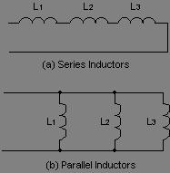
When inductors are connected in series, the number of turns is effectively increased. So too is the inductance, and the effective inductance of the circuit is the sum of the individual inductances.
The diagram shows series and parallel inductors. These calculations apply only to inductors which are not coupled magnetically. Where there is coupling between coils, the total inductance is also affected by the amount of coupling.
As with the resistor, for amateur radio examination purposes, you can visualise the resulting value of inductors like this:
Putting two inductors in series in effect increases the number of turns so the inductance value increases.
Putting two inductors in parallel, in effect decreases the effective inductance
Like the resistor, we can use visualised examples to easily work out what happens with two (or more) typical inductors of the same value. Put two in parallel, the value will halve. Put two in series and the effective inductance value will be double.
In a perfect inductor there is no loss of energy. The energy is stored in the magnetic field surrounding the inductor and (in an AC circuit) it changes in magnitude and sign twice in each cycle. The opposition to the flow of current is called the inductive reactance and is denoted by XL. Reactance is an opposition to current resulting from a storage of energy. The relationship is:
XL = 2π f L where f is the frequency in hertz, L is the inductance in henries, and XL is the reactance expressed in ohms. For our purposes, 2π can be taken to be the figure
Note that as the frequency rises, the inductive reactance also rises.
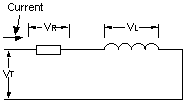
In practice there is no such thing as a perfect inductor and it is usual to consider the practical component to be a circuit containing both a resistor R (the inductor's resistance) and L the inductor.
Where resistance and inductance (inductive reactance) exist in a circuit together, they are combined into a term, called impedance, representing their combined total opposition to current flow.
Reactances can be added together directly. But resistances and reactances must be added together vectorially (as vectors), to get impedance. More about this follows below.
Types of inductors
Inductors used in radio can range from a straight wire at UHF to large chokes and transformers used for filtering the ripple from the output of power supplies and in audio amplifiers. Values of inductors range from nano-henries to tens of henries. It is convenient to group them into three categories.
Air core: to keep losses to a minimum it is necessary to keep the self-resistance of coils as low as possible.
This means using the thickest possible wire within the space available. Another reason for using thick wire or even tubing is to reduce the skin effect losses at high frequencies. 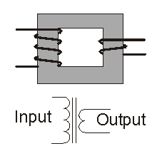 Direct current is spread uniformly over the cross-section of the conductor, but alternating current moves closer to the surface as the frequency increases.
Thus it is necessary to provide a large surface to minimise radio frequency resistance which is known as skin effect. Inductors used can range from a 25 mm diameter tube for a slot antenna on VHF to 50 turns of 22 swg wire on a 7.5 cm diameter former for the tank circuit of a 1.8 MHz transmitter.
The only adjustment available with air core inductors is by tapping all or part of a turn, or by varying the spacing between turns.
Ferrite or iron dust core: by inserting a ferrite or iron dust core in a coil it is possible to double its inductance. This means that it is also possible to halve the size of a coil for a given inductance. If the core is threaded, its position within the coil can be varied to alter the inductance. Some high-grade communications receivers have a system of cam-operated cores which are used for tuning. The type of material used for the cores or slugs is of importance and care must be taken to use the right grade for the right frequency band. This type of coil is used throughout the HF range, and into the VHF, for low-level signal circuits. Losses in the cores make them unsuitable for use in power circuits. Values range from a few microhenries to about a millihenry.
Similar types of coils have been made using brass cores instead of ferrite. The effect of this is to reduce the inductance by about 20%. They also increase the losses.
Iron core: this classification includes chokes and transformers, both of which have laminated iron cores. Transformers are described in the next section. A choke is a single winding and a transformer has two or more windings. Typical values of inductance for chokes range from 0.1 of a henry to 50 henries.
It’s really a nice and helpful piece of info. I am glad that you shared this helpful info with us. Please keep us up to date like this. Thanks for sharing.
I love the blog.
I just want to say I am just beginner to blogging and seriously loved your web blog. Likely I’m going to bookmark your blog . You amazingly come with amazing writings. Thanks a bunch for sharing with us your blog site.