MCQs of Basic Electronics 50 Questions
Basic Electronics questions and answers with explanation for interview, competitive examination and entrance test.

MCQs of Basic Electronics 50 Questions
Basic Electronics questions and answers with explanation for interview, competitive examination and entrance test.
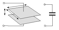
Example:  Circuit symbol:
Resistors restrict the flow of electric current, for example a resistor is placed in series with a light-emitting diode (LED) to limit the current passing through the LED.
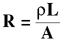
Resistivity Calculation – The electrical resistance of a wire would be expected to be greater for a longer wire, less for a wire of larger cross sectional area, and would be expected to depend upon the material out of which the wire is made (resistivity). Experimentally, the dependence upon these properties is a straightforward one for a wide range of conditions, and the resistance of a wire can be expressed as
Resistance and Conductance
Resistance

|
The electrical resistance of a circuit component or device is defined as the ratio of the voltage applied to the electric current whichflows through it:
If the resistance is constant over a considerable range of voltage, then Ohm's law, I = V/R, can be used to predict the behavior of the material. Although the definition above involves DC current and voltage, the same definition holds for the AC application of resistors. |
Mcqs Electronics Engineering
1. When four resistances of 2W 1W; 5W 2W; 10W 5W and 15W 10 W are connected in parallel, the greatest power is absorbed by
2. A moving coil instrument has a resistance of 10 W and gives full scale deflection when carrying a current of 50 mA. To measure current upto 100 A, we will have to connect
3. The ripple voltage in the output of a single phase half wave rectifier with 10 V rectified dc voltage with resistive load and without filter will be
Mcqs in Basic Electronics test paper
1.When four resistances of 2W 1W; 5W 2W; 10W 5W and 15W 10 W are connected in parallel, the greatest power is absorbed by
2. A moving coil instrument has a resistance of 10 W and gives full scale deflection when carrying a current of 50 mA. To measure current upto 100 A, we will have to connect
Basic Electronics mcqs paper 1
1. Voltage across 4 ohm resistance in respect of the following drawing circuit

will be
a) 12 V b) 6 V
c) 4 V d) 20 V
Electric Transformer Theory
Any two coils magnetically linked will act as transformers. Transformers come in as many forms as inductors, air or dust cored as well as the more familiar iron-cored type. The iron-core can take several forms.
The simple transformer comprises two or more inductors (windings) sharing a common core. See Power Supplies for an explanation.
An alternating current is fed to one of the windings. The operation can explained by considering the magnetic field of the input winding, the primary, sweeping through the secondary winding to induce an AC current in the secondary. These principles are considered in AC
The "turns ratio"
A common task for a transformer is to provide an AC supply at a voltage suitable for rectifying to produce a stated DC output.
Inductors Resonance
We'll start with the inductor!
 The Inductor
This figure shows a conductor carrying a current. A magnetic field is set up around the conductor as concentric circles.
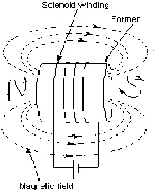
If a coil of wire has a current flowing through it, the magnetic flux due to each turn will link with every other turn and produce the same sort of magnetic field as a permanent magnet. Such a coil is called a solenoid as shown here. It acts as a magnet only when current is flowing through it.
The magnetic polarity of the solenoid can be determined from the 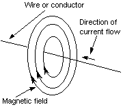 direction of current flow as seen looking in the ends, as shown in the diagram. From that the direction in which the magnetic field is acting can also be found.
Solenoids or electromagnets are widely used in electronic equipment. Loudspeakers, headphones, moving coil microphones, measuring instruments, transformers and such things, depend on electromagnetism for their operation.
A inductor may be air-cored or have a solid core.
