Electric Transformer Theory
Any two coils magnetically linked will act as transformers. Transformers come in as many forms as inductors, air or dust cored as well as the more familiar iron-cored type. The iron-core can take several forms.
The simple transformer comprises two or more inductors (windings) sharing a common core. See Power Supplies for an explanation.

An alternating current is fed to one of the windings. The operation can explained by considering the magnetic field of the input winding, the primary, sweeping through the secondary winding to induce an AC current in the secondary. These principles are considered in AC
The "turns ratio"
A common task for a transformer is to provide an AC supply at a voltage suitable for rectifying to produce a stated DC output.
The number of turns on each winding determines the output voltage from the transformer. The output voltage from the secondary is proportional to the ratio of the turns on the windings.
For example, if the secondary has half as many turns as there are on the primary, and 100V AC is applied to the primary, the output from the secondary will be 50V.
Transformers can be step-up or step-down (in voltage). With twice as many turns on the secondary as there are on the primary and 100 V applied, the output would be 200V.
The impedance ratio is proportional to the square of the turns ratio. We can use transformers to change impedances. This property is one of the most important properties in the use of transformers.
The power output from the secondary winding cannot exceed the power fed into the primary. Ignoring losses, a step-down in voltage means that an increase in current from that lower-voltage winding is possible. Similarly, a step-up in voltage means a decrease in the current output. So the gauge of wire used for the secondary winding may be different to the wire used for the primary. (The term "gauge of wire" relates to its cross-sectional area.)
Iron-cored transformers are used for audio frequencies and for power supplies. Audio frequency transformers are designed to give suitable efficiency to frequencies up to 25 kHz. For speech and domestic quality radio reproduction the core material used is stalloy, while the laminations of high-fidelity transformers are made of mu-metal The construction is the same as for chokes and the same considerations of size and power rating apply.
Transformer losses
There are two main types of loss in a transformer, the iron loss and the copper loss. Copper loss is due to the resistance of the wire used for the windings. Copper loss can be reduced by using large diameter wire for the windings, but there is a limit to the size and weight and some copper loss is unavoidable.
 One of the principal iron losses is caused by "eddy currents" flowing in the core. The magnetic circuit (core) can be considered to be a one-turn coil and heavy currents could flow causing very high losses. To reduce this eddy current loss the core is made up from many thin slices of iron called laminations which are insulated from each another.
Toroidal core transformers
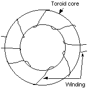
 If the core of a transformer is of specially-selected material and is formed into a complete loop as shown in this diagram, nearly all the flux lies within the core and there is very little leakage, or flux outside the core.
This results in very little unwanted coupling to adjacent magnetic circuits, and is a very desirable feature in some circuits. An application is in the common SWR Bridge. MEASUREMENTS
Electric Transformer Theory
